
Marathon aircraft: what if humans could really fly?
- Skills demonstrated: Aerodynamics, programming, project management, mechanical design, electronics design, composites manufacturing
- Tools used: Arduino, C, Python, Xfoil, Xrotor, Solidworks
- Company/Team: University of Toronto HPVDT
- Project date: 2020-2021
- Competition Information: The Kremer International Marathon Competition
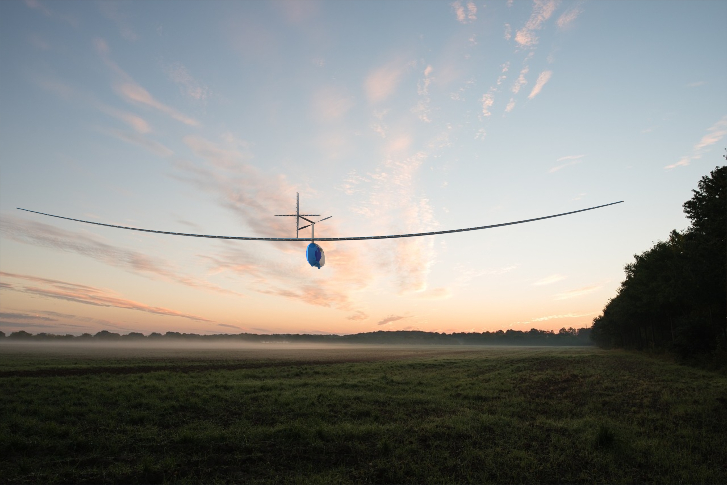
In 2020, my friend Calvin and I decided to participate in the Kremer International Marathon Competition hosted by the Royal Aeronautical Society.
This competition is an open challenge that consists of developing a human-powered aircraft (HPA) to travel along a specified 40-km path in less than one hour. We started the
project as co-captains of the Human Powered Vehicles Design Team in 2020. This summer (2021), we recruited the most capable
engineering students to manufacture and test the plane. We plan to do our flight attempt in September.
I worked closely with my co-lead to select the configuration of the aircraft; we opted for a tandem style where two cyclists provide power to a rear-mounted propeller.
I designed
the in-flight electronic system along with two other team members - more details on this subsystem in another section.
As team manager, I had to coordinate tasks, review the designs of other
team members, and coordinate with the faculty to develop a safety test plan.
The most efficient low-speed propeller ever.
- Skills demonstrated: Programmming, mechanical design, aerodynamic design
- Tools used: Python, Solidworks, Xrotor, Xfoil
- Company/Team: University of Toronto HPVDT
- Project date: 2020 - 2021
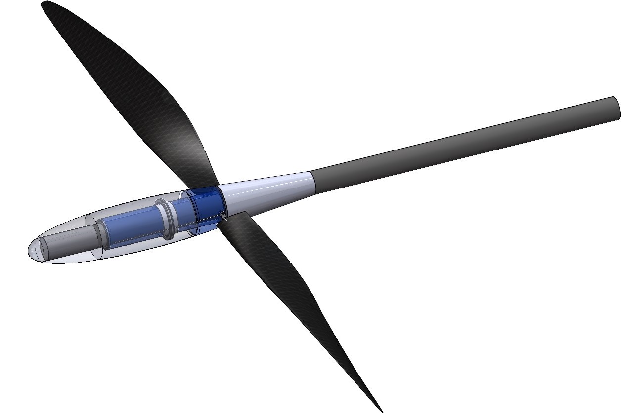
My team is competing for the Kremer International Marathon Prize, and I designed our propeller. I started this project knowing little about propellers and aerodynamic design. However, during those years,
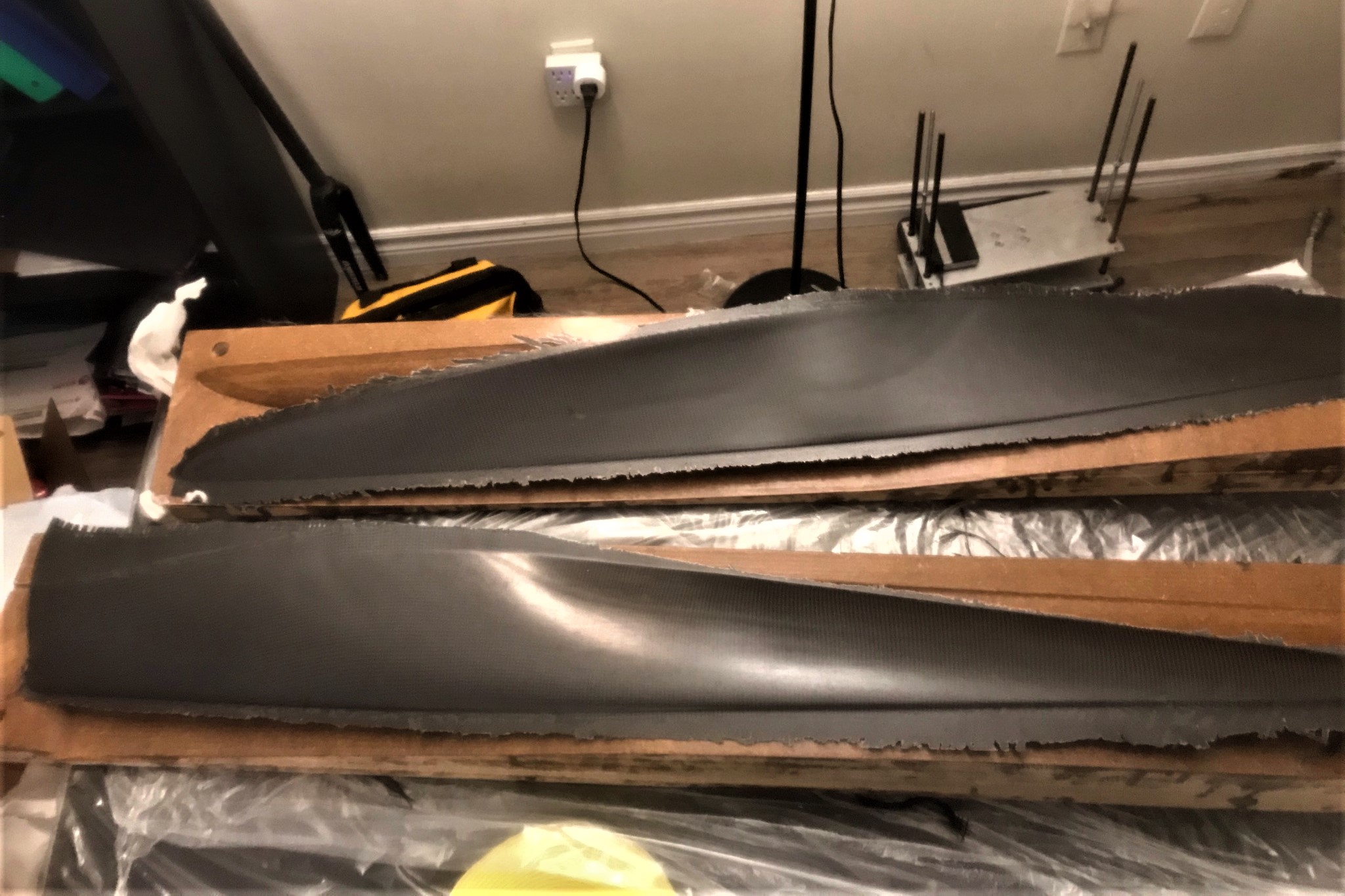
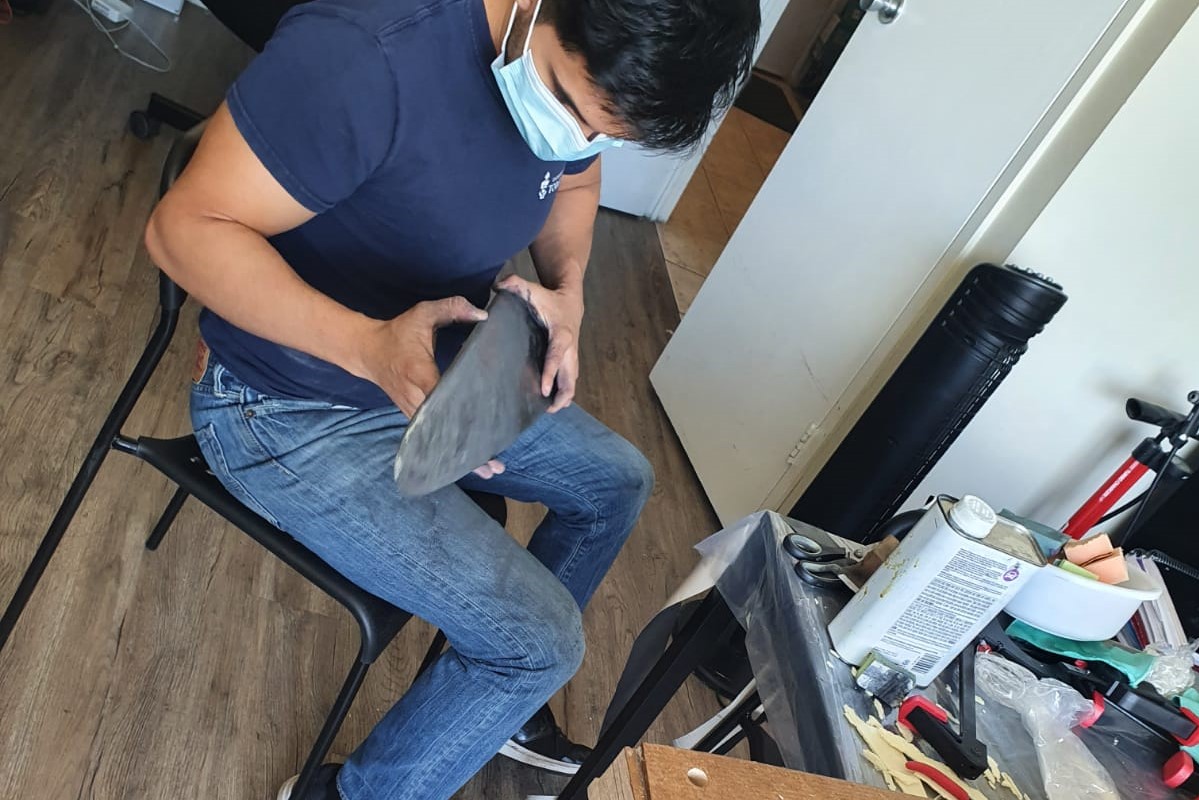
I learned enough to create a design tool that finds the most suitable propeller configuration and shape for our design conditions. The design tool was tested by prototyping a propeller. The
results were satisfactory.
This propeller design tool combines Python, Xfoil, Xrotor, and Solidworks. The inputs to the Python program are the desired flight speed, thrust, candidate airfoils to analyze, and other few parameters.
The output is a Solidworks macro to design a blade of the most efficient propeller possible within the design constraints. The program uses Python parallel processing libraries
to reduce computing time.
Human-powered aircraft flight controller and sensors.
- Skills demonstrated: Electronic design, programming, mechanical design
- Tools used: C, Solidworks
- Company/Team: University of Toronto HPVDT
- Project date: 2021
- Video URL: https://youtu.be/AetwIezSxqg
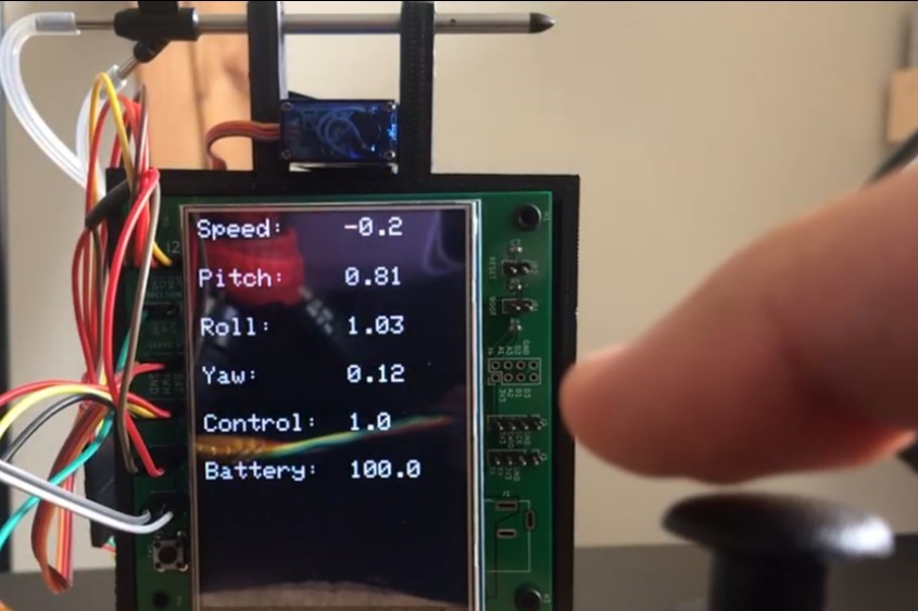
The objectives of this project were to design a system that translates pilot input into accurate movement of the control surfaces of a human-powered aircraft (HPA), gathers speed data,
and provides a visual medium to communicate in-flight data to the piots. Other design objectives were to minimize weight and volume.
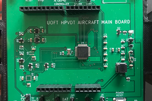
The final design featured a 9 DoF IMU, barometer,
differential pressure sensor, servo motors, and a display. The main microcontroller was an STM32F103, and the secondary boards, which will be added as needed, use an ATmega328P - the same found in the Arduino Uno.
My primary role in the project was to write the code in C, select the sensors, and build a prototype.
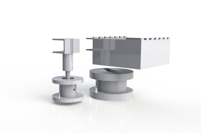
Cooling shroud for metal powder reactor.
- Skills demonstrated: Mechanical design, design for manufacturing, CFD
- Tools used: Solidworks, Ansys
- Company/Team: University of Toronto CACT Laboratory
- Project date: 2020 - 2021
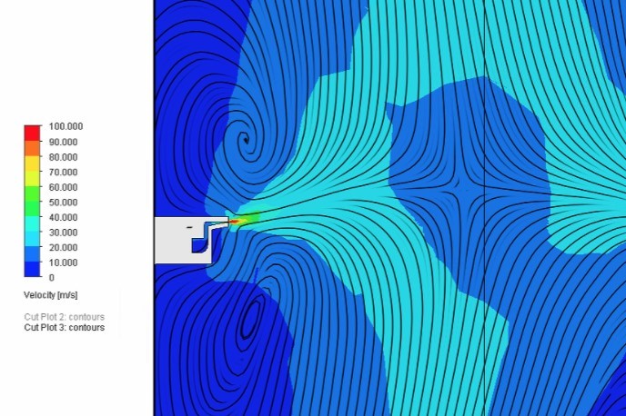
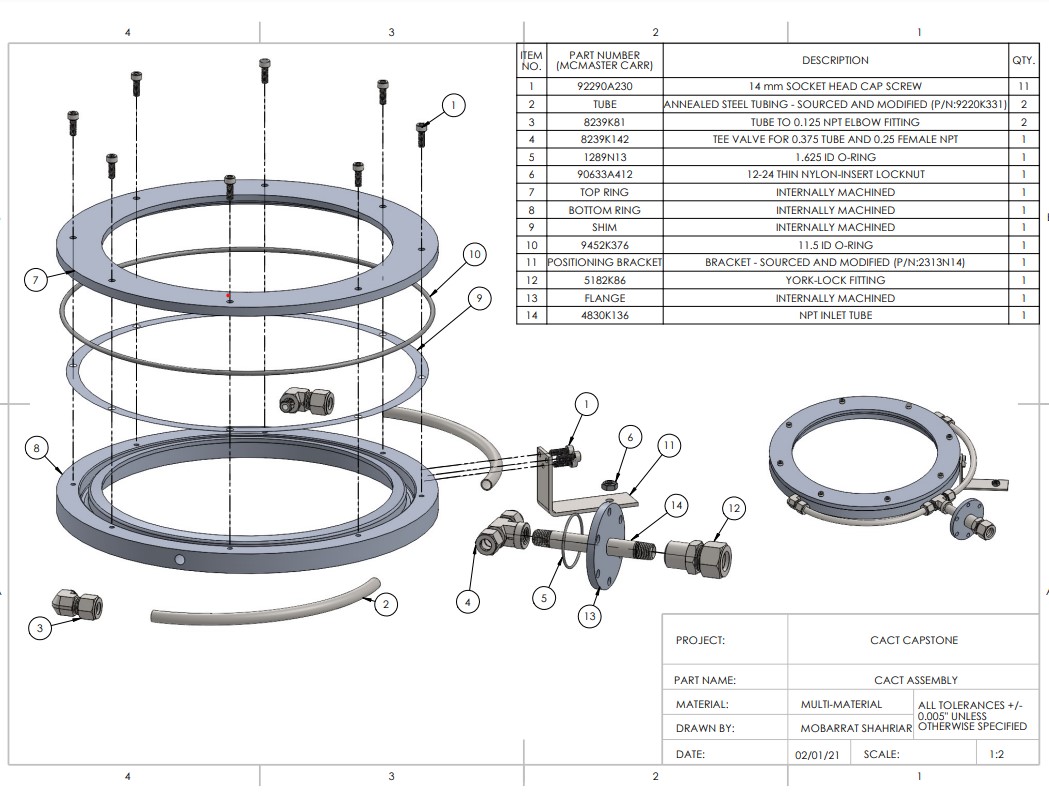
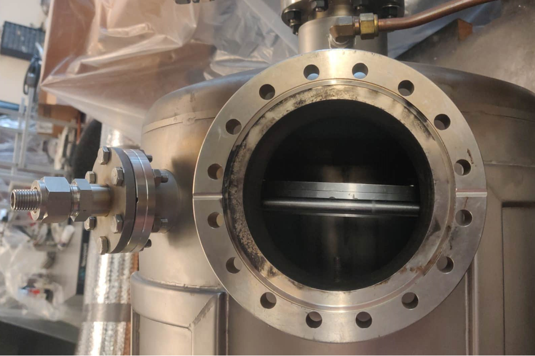
The Center for Advanved Coating Technologies (CACT) develops state-of-the-art thermal spraying techniques. They were lacking an effective cooling system for their reactor used to produce metal powder. This was important because the cooling
process directly impacts the quality of the powder. Our design distributes nitrogen evenly and at high speeds inside the chamber, increasing the cooling rate and reducing contact with oxygen, which in turn reduces oxidation and results in smaller and more desirable sized particles.
The work was distributed evenly among the three members of my team. I did part of the design in Solidworks, manufacturing drawings, and all of the fluid simulations. The design was built by a university shop and tested by my team at the CACT facility.
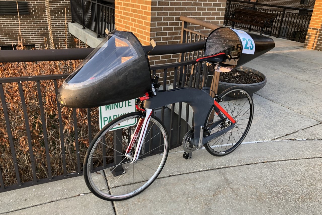
TITAN: The fastest tandem speedbike ever built.

- Skills demonstrated: Electronic design, mechanical design, composites manufacturing
- Tools used: Solidworks, Arduino
- Company/Team: University of Toronto HPVDT
- Project date: 2019-2020
- Video URL: https://youtu.be/uYFdVVKSzns
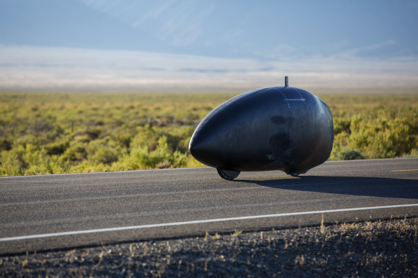
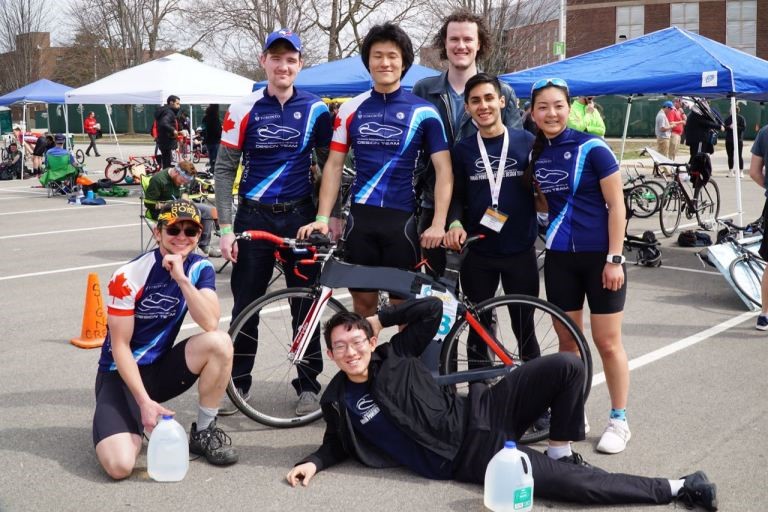
At hpvdt.skule.ca, we build carbon fibre bicycles that break world records of speed and engineering while promoting sustainable transportation. In September of 2019, TITAN travelled at 74mph, becoming the fastest tandem in history at the World Speed Challenge.
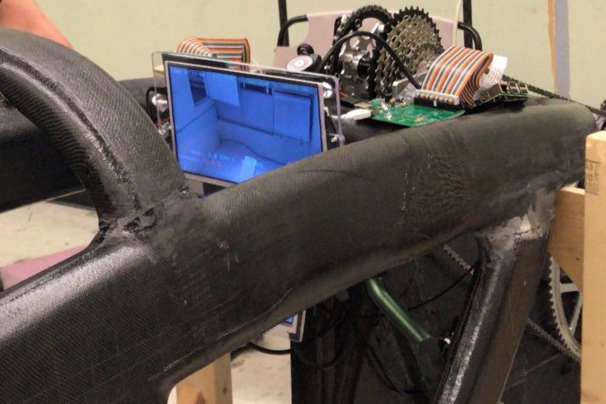
My main work with TITAN was designing speedometers, using GPS and light sensors, as well as creating housings to secure the electronic system to the bike. This vehicle is fully closed, and the cyclists rely on cameras for visibility, so it is essential to keep cameras and displays secure and stable.
I also participated in the manufacturing process by building moulds, composite structures, and jigs.
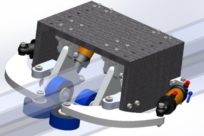
Suspension system for non-levitating hyperloop pod.
- Skills demonstrated: Mechanical design, FEA, dynamic analysis
- Tools used: Ansys Mechanical, Solidworks, CNC mill
- Company/Team: University of Toronto Hyperloop Team
- Project date: 2020
- Video URL: https://vimeo.com/409042018
The University of Toronto Hyperloop Team (UTHT) is designing its first hyperloop pod, which will run on a straight test track (no levitation).
The vehicle is expected to reach speeds of 100 km/h or higher. There might be severe irregularities on the track that will introduce vibrations and change the direction of the pod - the pod cannot steer.
The function of the stability system is to counteract the effects of these irregularities and maintain the pod aligned with the track.
I started by creating a mathematical model to predict the accelerations of the pod in the vertical and lateral (perpendicular to the track) directions. I made a tentative design that consisted of two subassemblies located
underneath the pod. Each of these subassemblies introduces shock absorbers between the pod and the track, reducing vibrations; their combined effect prevents
rotation in roll, pitch, and yaw. Then, I conducted harmonic analysis on Ansys.
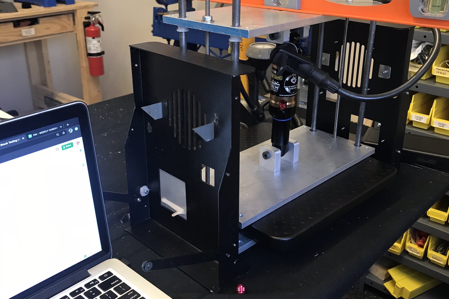
Using these tools, I finalized the detailed design and calculated suitable spring constant and damping coefficients. Finally, I sourced components and
designed experiments to validate my design safely and economically. I also built a testing rig to validate the mathematical model of the air shocks I selected.
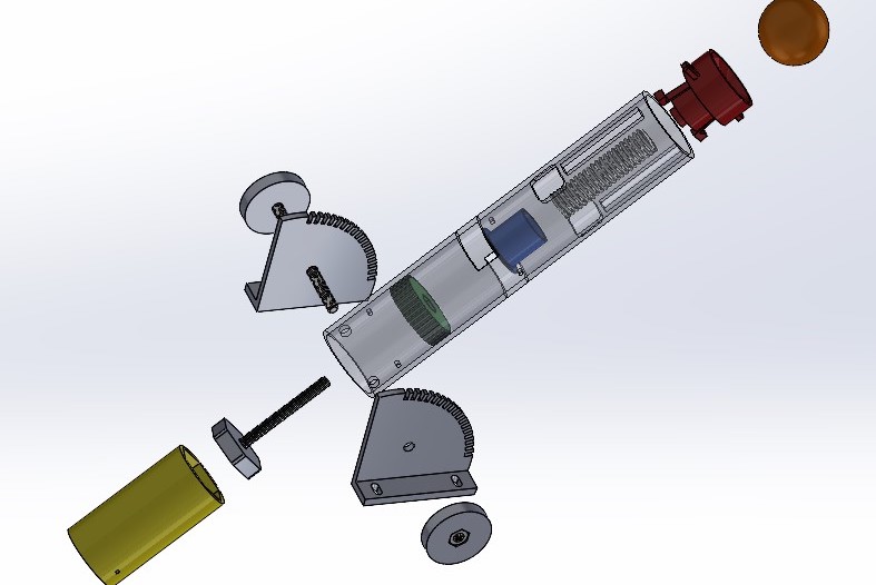
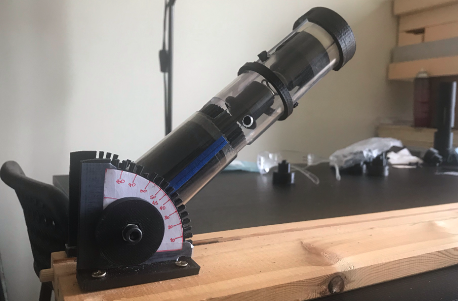
DOE applied to a ping pong-ball cannon toy.
- Skills demonstrated: DOE, mechanical design, tolerance analysis, FEA, 3D-printing
- Tools used: Solidworks
- Company/Team: University of Toronto
- Project date: 2021
The goal of this project was to design a toy that could launch a pingpong ball to a target distance between 2-6 m. The features of the toy
were optimized using design of experiments (DOE) techniques. My team employed several design tools like structured brainstorming techniques, Pugh matrix, house of quality (HOQ),
functional decomposition, FMEA, latitude study, and tolerance analysis.
My main responsibilities in this project were the complete detailed design of the toy, construction of the prototype, execution of
the experiments and analysis of the results. I used FEA to predict the stresses on structural plastic components and utilized this information to design them to maximize
their strength-to-weight ratio.
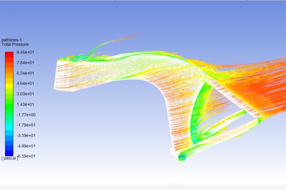
Zephyr: upright bike beats all other speedbikes at ASME E-fest.
- Skills demonstrated: Aerodynamic design, composites manufacturing
- Tools used: Solidworks
- Company/Team: University of Toronto HPVDT
- Project date: 2018 - 2019
My team realized that the ASME E-Fest HPV Competitions were increasingly focusing on practicality and maneuverability rather than speed. However, all the teams continued to build aerodynamically optimized recumbent bikes, a configuration
that is not adequate for this design objective. We decided to change our strategy and built a 'typical' upright bike instead, while still trying to reduce drag via fairings that covered most of the cyclist frontal area. This worked well.
We won every athletic event and got second place overall.
My role as ergonomics lead was to ensure our biked was adequately size for all cyclists in our team. I designed a realistic human model with variable height and body proportions
to accomplish this goal. I also used this model to simulate the drag created by the body. I used Ansys Fluent to analyze the effects of the fairings and reduced drag by 30% from the first to the last iteration. This was later validated with a prototype.
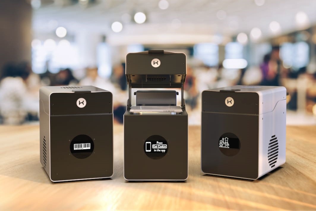
Accelerated lifecycle testing robot for IoT smart cooker.
- Skills demonstrated: Design of experiments, electronic design, mechanical design
- Tools used: Arduino, Onshape
- Company/Team: KitchenMate Inc
- Project date: 2019-2020
At KitchenMate, I was part of the product development team working on the next-generation smart cooking appliance. We were concerned with the performance of the electronic devices that moved during normal operation. Previously, we had manually tested
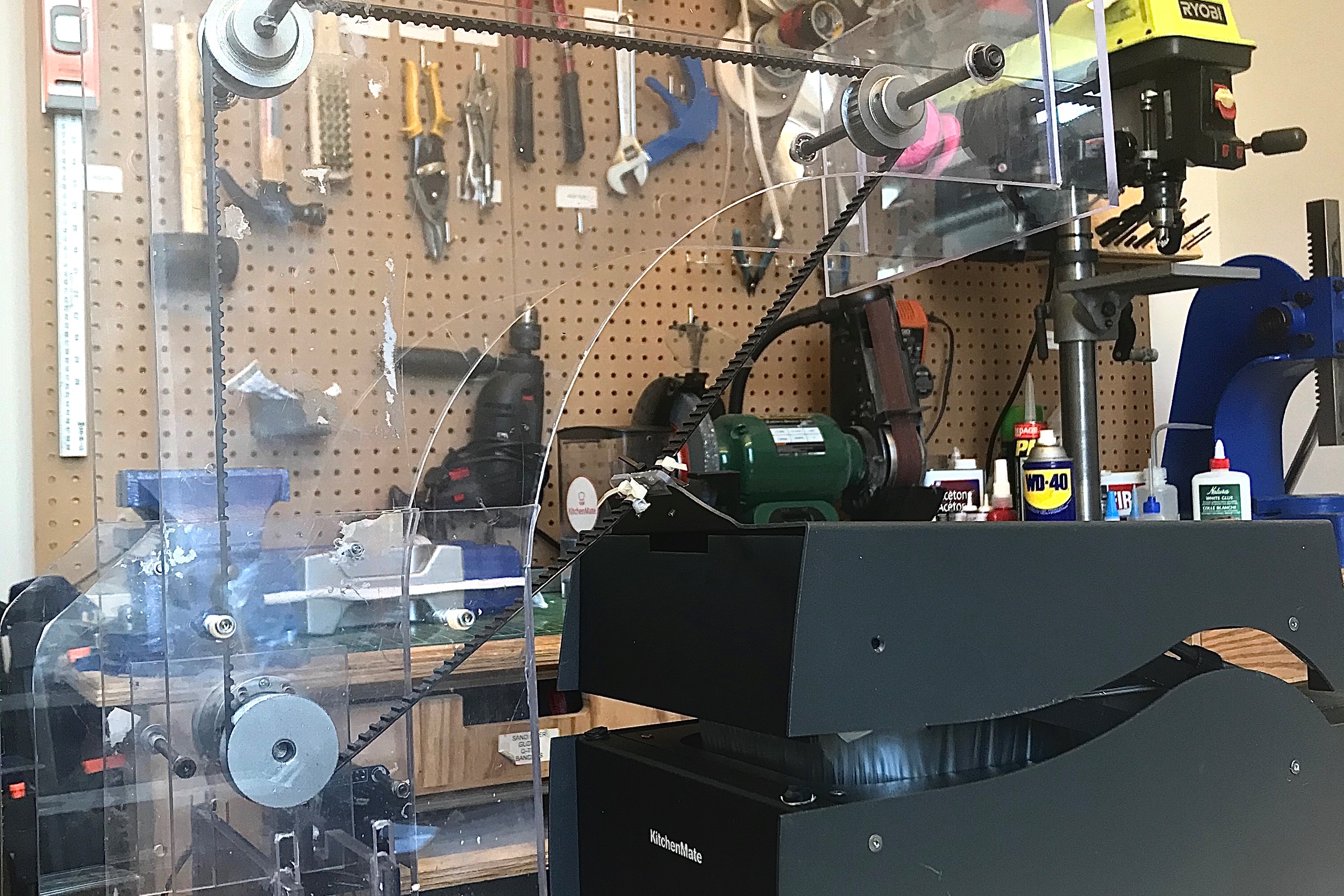
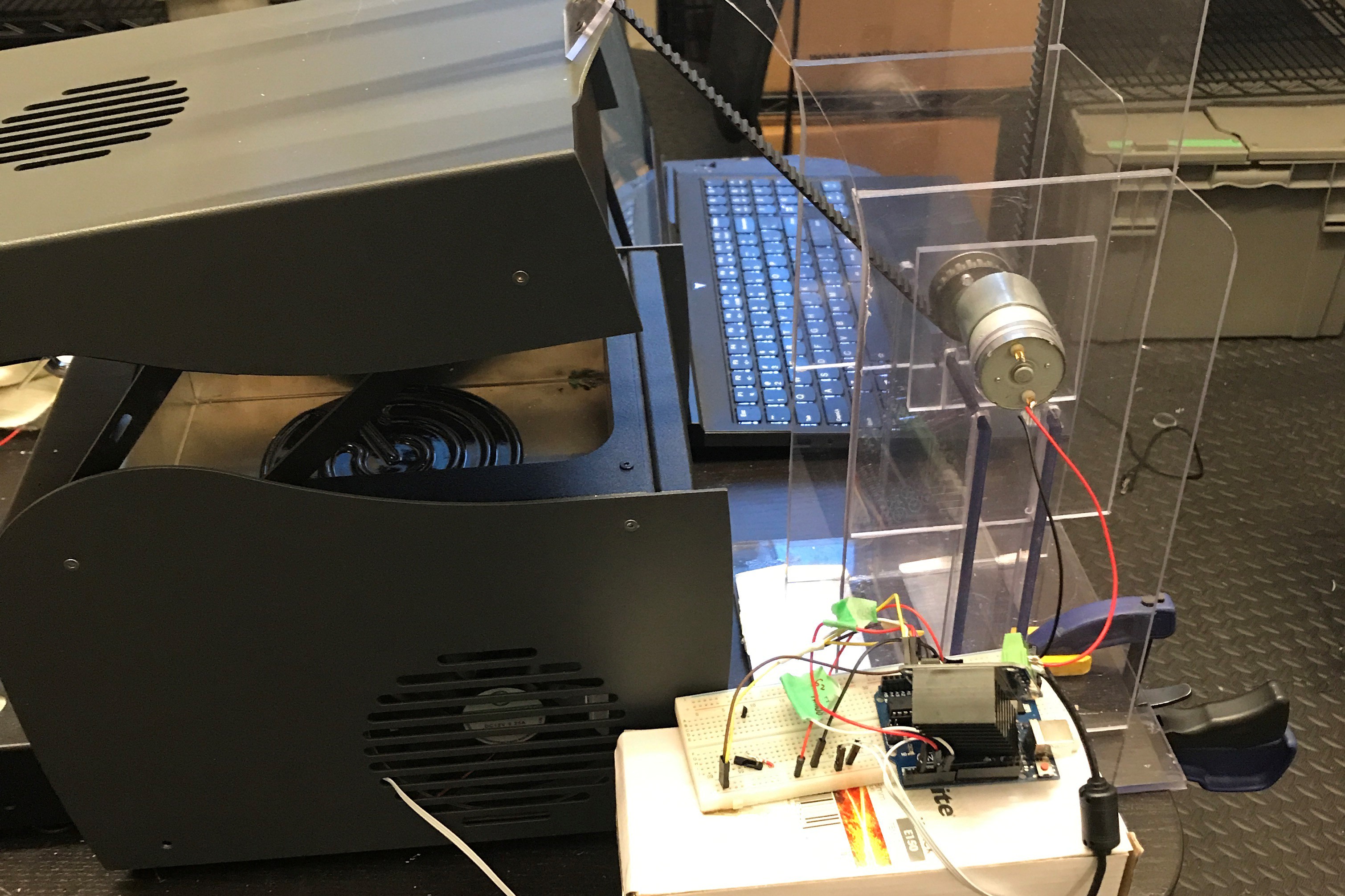
the long-time performance of the appliance in our office, but this tool several weeks. To speed up this process, I created a robot to actuate the machine, simulating a user while the software was running. This allowed us to test over 35,000 cycles - more than the expected use over 5 years - in just a few days. The
speed of the tests was limited by the cooker's software. This revealed multiple sources of failure, which we mitigated in later iterations.
For this project, I used an Arduino, DC motor, and motor driver. The machine was connected to the smart cooker to detect
when the door was closed. The Arduino monitored the status of the smart cooker components, and the test would stop if any component failed.
Bluetooth-controlled curtains for my room.
- Skills demonstrated: Electronic design, mechanical design
- Tools used: Arduino, Solidworks
- Company/Team: Personal project
- Project date: 2018
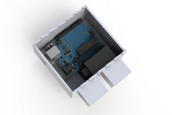
I have always been attracted to home automation, especially being able to control things from my phone. Following this interest, I
built a system of pulleys and servo motors to open my room's curtains in the morning.
I first calculated the force needed to pull the curtains, the size of the pulley, the motor's torque and speed requirements, and found adequate components available in the market.
Everything was designed to fit in the space I had available and only used mounting hardware already installed for the curtains. The motors were controlled by an Arduino, which connected to my phone
via Bluetooth.
Compact smartphone stand to see slides during class.
- Skills demonstrated: Mechanical design, 3D-printing
- Tools used: Solidworks
- Company/Team: Personal project
- Project date: 2018
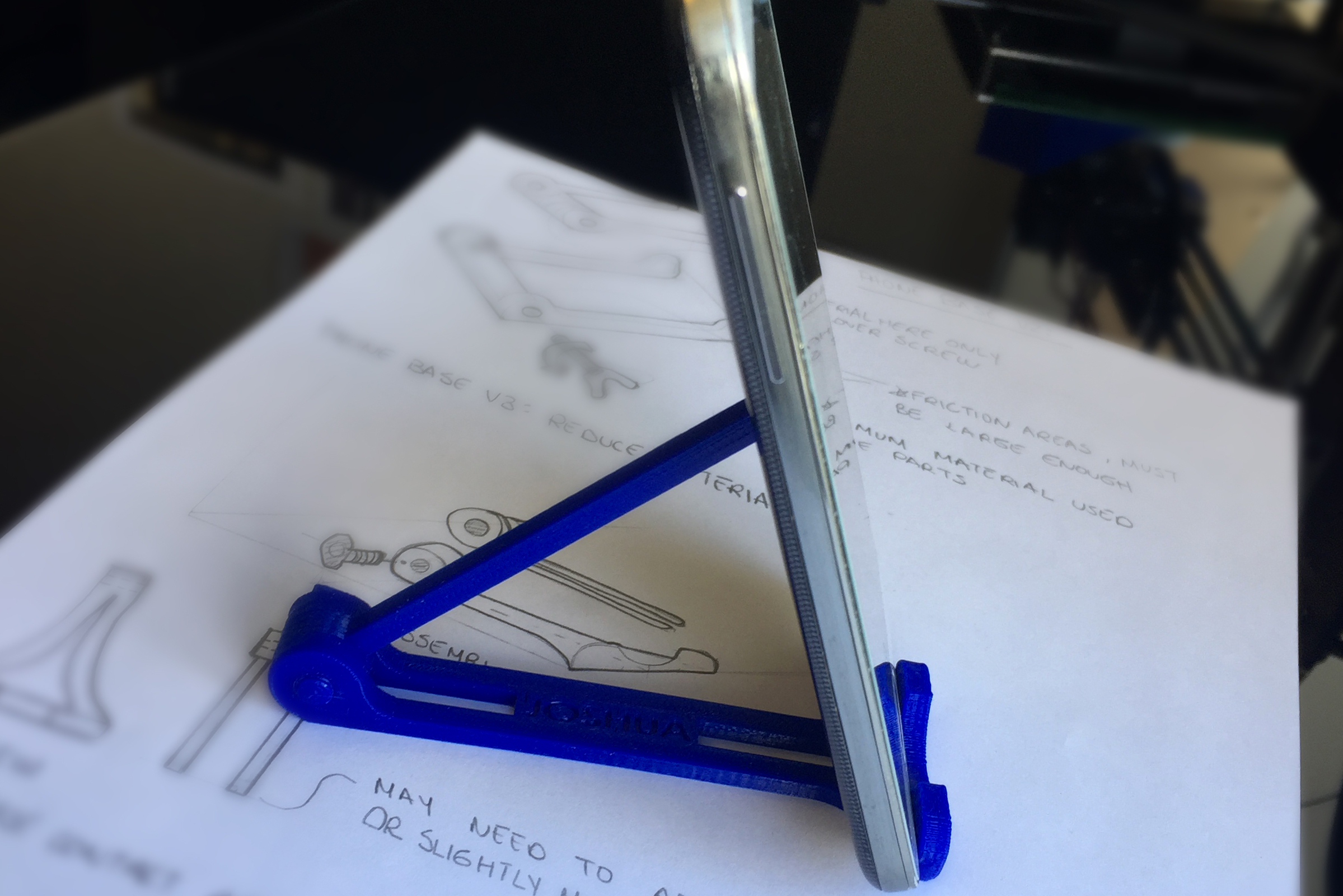
At UofT, professors post their lecture slides in advance, and I like having them during class. However, printing them
wastes paper, and the lecture-hall tables are too small for a laptop, so I had to use my phone. This worked fine, but it was very
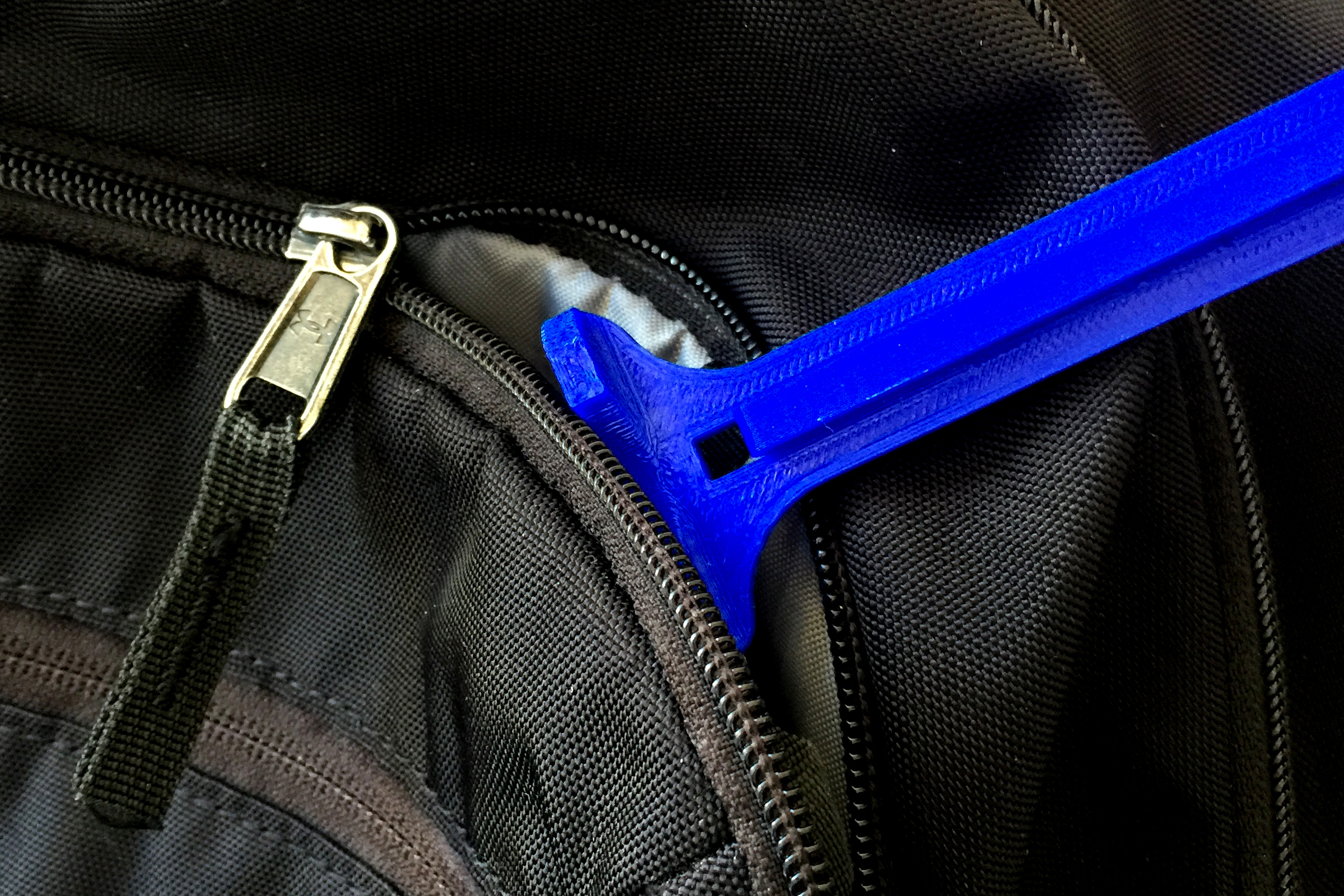
uncomfortable looking straight down all the time. I couldn't find a good phone stand that fit in my backpack or the table, so I decided to make my own.
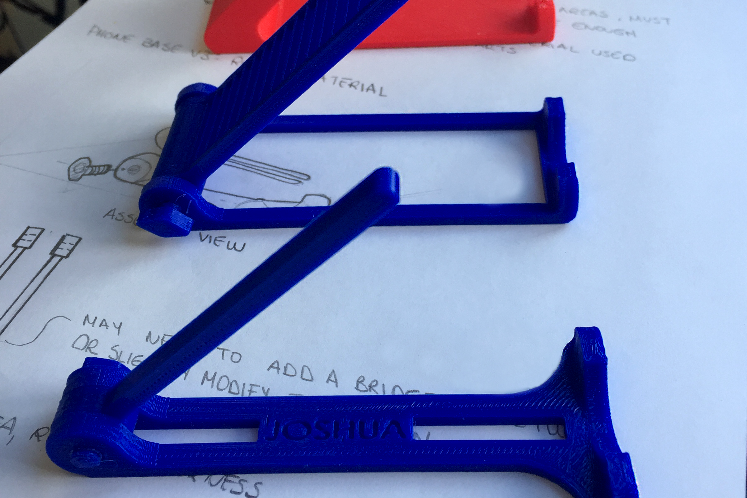
That semester, I designed and tested several design concepts that met the size constraints. My goal for each iteration was to
minimize material use, weight, and base area. They were also designed to work with any phone. To allow for different angles and phone sizes, I
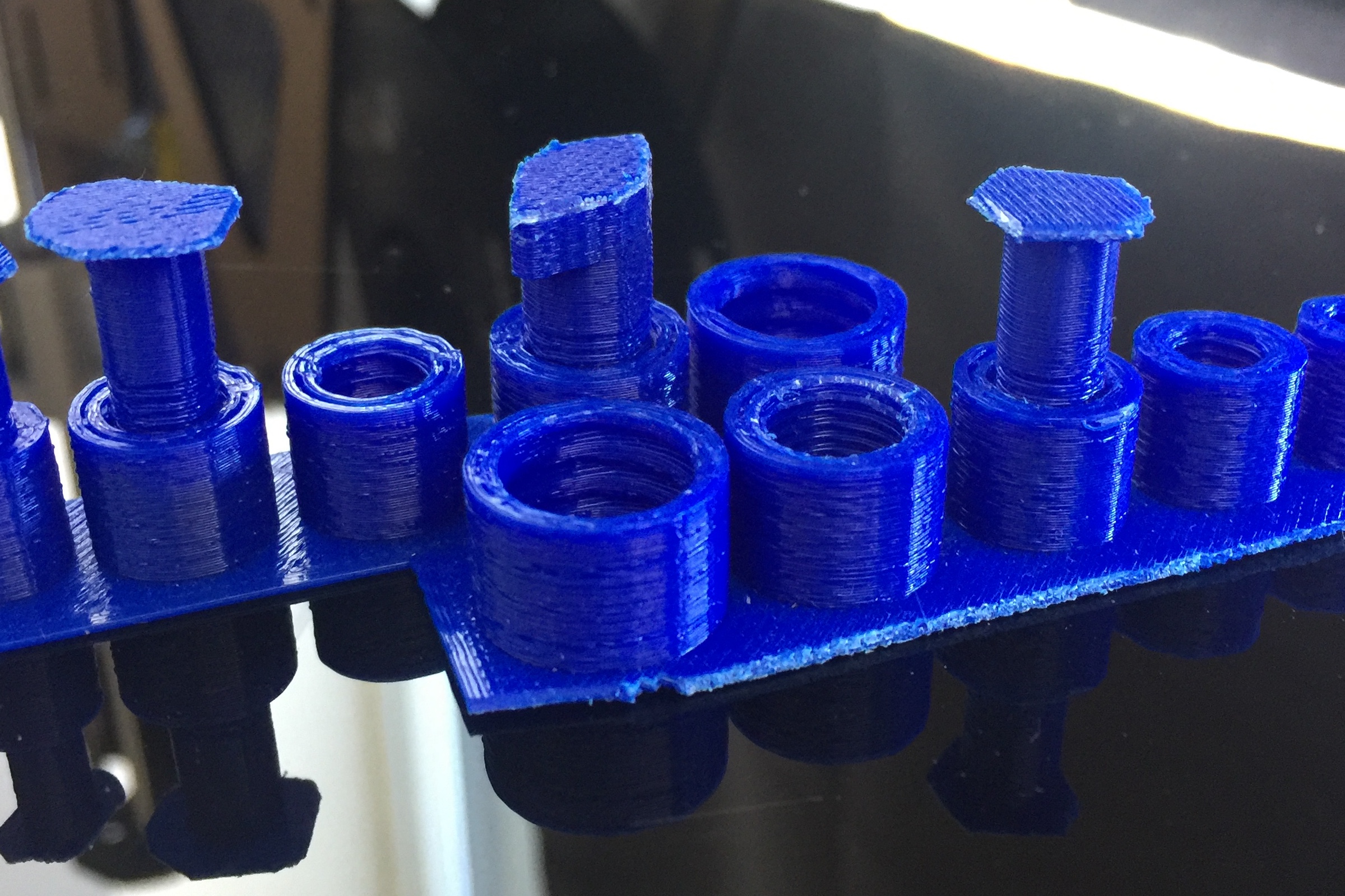
experimented with 3D-printing tolerances to make screws and nuts to allow parts to move and lock in place. The project was successful, and
I also built some extra for my friends who also found it useful.
3D-Printer design.
- Skills demonstrated: Mechanical design, GD&T
- Tools used: Solidworks
- Company/Team: University of Toronto
- Project date: 2017
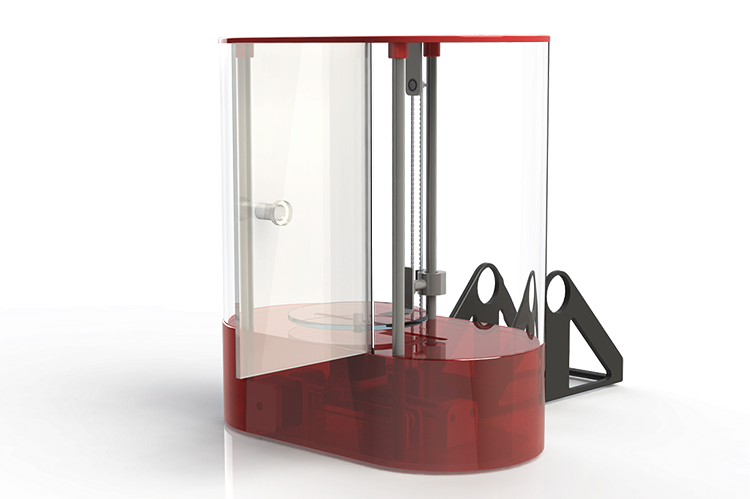
As part of a course project, I led a team of 5 people to design a fully functional extrusion 3D printer. The product was intended for home
and hobby use. Thus, we optimized for reliability, ease of assembly, and ease of operation. The results were evaluated based on objectives
established during the first design stages.
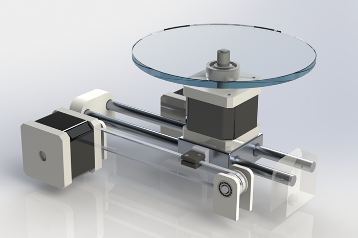
My team chose mechanisms to meet the design criteria of fit, price, and mechanical properties. Parts available in the market were favoured,
and many others were designed by my team. I was responsible for the detailed design of the bottom subassembly and integration of the subassemblies
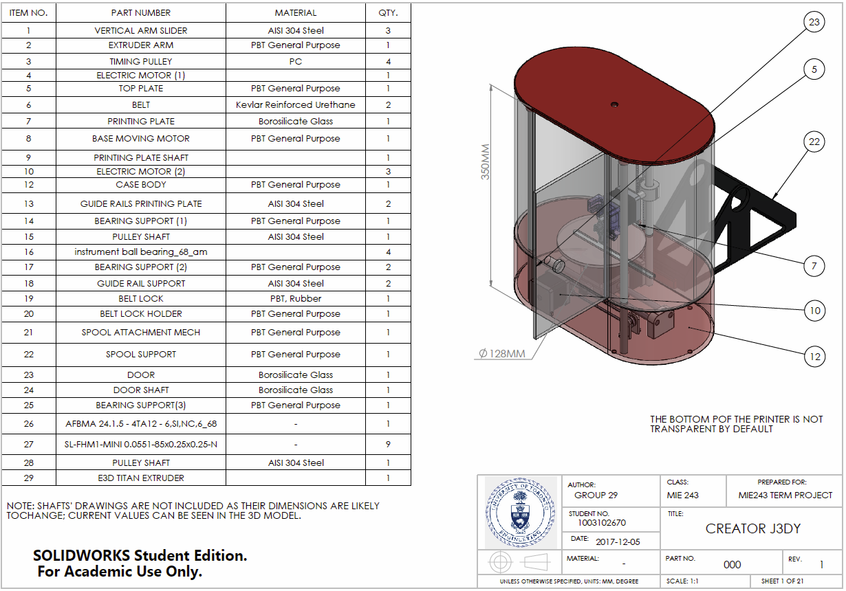
into the master assembly. My team used Solidworks to design and simulate the operation of the printed. The design was documented through
a detailed engineering report, 3D models, drawings, and an oral presentation.